Ryzen 7 overclocking the 3700X
AMD Ryzen 7 3700X overclocking guide.
This is an easy to use and comprehensive overclocking guide for the AMD Ryzen 7 3700X with a wide
RSS feed for Technology, Overclocking, and SEO articles.

This is an easy to use and comprehensive overclocking guide for the AMD Ryzen 7 3700X with a wide range of illustrations. Both the manual overclocking and the AMD PBO 2.0 feature is covered in this guide for the AMD Ryzen 7 3700X.
This setup is intended for my home server below are some of the parts I mainly use for overclocking. The difference is a 2666C16 64Gb kit and no GPU when this is moved over into the server case. For the server, the tweaked PBO 2.0 profile described below will be used as it will be the most power-efficient while retaining most of it boost potential. Of the bat, I will say overclocking the Ryzen 3000 series does not see an awful lot of gains unless you also want to overclock the memory with the CPU. In the case of manually overclocking a DDR4 overclocking guide located here: Overclocking guide for DDR4 RAM to unlock the full potential of the 3700X. For most users using the PBO 2.0 features will be the fast and easy route to take.
Make sure you have the latest chipset drivers and other drivers for your current setup. Using outdated drivers may cause instabilities not related to your overclocking. In this guide, a preset 3600C15 XMP profile was used @ 1.25v of 16GB. Consider running a synthetic benchmark with stock settings to measure your gains as well as in this case, ensuring the stock CPU and memory that is running XMP is fully stable. When using a complete new DDR4 kit, this is not advised, and it is recommended that you overclock your CPU first and then overclock the DDR4 RAM kit of your choosing. As well as if you intend to do any gaming have a baseline of FPS so you can see the increase in performance.
You also want to download the following programs for stress testing your overclock. These are a vital tool for stress testing and monitoring if you already have tools you can use those but these programs I highly recommend and were used while writing this overclocking guide and many other overclocking guides on hisevilness.com.

Zen 2 offers greater stability then the previous Zen architectures and can be used running a stock XMP profile. Do make sure that the DDR4 kit is listed on the QVL list of your respected motherboard. So you can select the XMP profile and make sure the right XMP profile is selected. For this motherboard, the listed XMP profile, in general, is 3466Mhz. However, the XMP profile of 3600C16 can be selected and works just fine. If your DDR4 kit is not listed on the QVL list, then it would be wise to turn on the XMP profile and do a Prime95 or Linpack Xtreme stress test first to make sure the XMP profile is stable.

The AMD 3000 series works really well with PBO, and it can be the safest and fastest way to overlock any 3000 series CPU. PBO 2.0 offers much finer control over the auto-overclock feature.
There some settings in the BIOS that can be adjusted to use AMD's Precision Boost Overdrive 2.0 to gain the best results some tweaks are needed for a longer boost duration and overriding some limitation from within the BIOS. Important with PBO 2.0 is how the Precision Boost Overdrive Scalar works with the PPT, TDC and EDC. To run a Scalar 10, you will need to tweak the PPT, TDC and EDC settings. If opting for a lower Scalar PPT, TDC and EDC can be left on Auto or maxed out.
The image below is an example profile of the 3700X running a base PBO 2.0 profile reaching 4.35 GHz max all cores and under sustained load with Prime95 Small FFT's 4.20 GHz all cores. And a max single core of 4.425 GHz single-core with Prime95 Small FFT's.

A feature on the ASUS motherboard is the Fmax Enhancer by The Stilt this helps single-core performance. It can be enabled in the normal PBO menu as highlighted below.

With some further tweaks, some more gains could be made, but those gains were minimal. 4.35 GHz max all-core with a sustained all core max of 4.3 GHz. And a max of 4.475 GHz in single-core. This also might be because of the limitation of the VRM on a B450 motherboard so X470 or X570 motherboard results should be far better. Another option here is to tweak the VRM settings as would normally apply when manually overclocking. The Digi+ VRM settings below covers that more in-depth to squeeze just a bit more performance out of your AMD 3700X.

In preparation for the overclocking of the AMD 3700X, some settings for the VRM need to be adjusted for stable overclocking. This portion also covers some settings for overclocking memory regarding the SoC portion of the VRM. When overclocking with a different brand of a motherboard, the LLC levels might be different, but in short, you want to have as little Vdroop as possible. Other brands might reverse the numbering for LLC where 1 has the least Vdroop and 6 the most etc.

Furthermore, a couple of settings need to be turned off for manually overclocking the AMD 3700X. In this particular BIOS, these settings are presented twice in various menu's. If left on these might introduce instability in the manual overclock.
Under AMD CBS turn off Core Performance Boost and Global C-State Control as shown in both images below, there are 2 menu's you will need to browse to in the particular B450 motherboard.


Then go to Precision Boost Overdrive and turn that off as shown in the images below, there are 2 settings menu for this portion as well.


Now for the final part after a bit of preparation, and see how far the 3700X can manually overclock. Make sure not to exceed to voltage limited either set by AMD or the Overclocking community. For a save daily use, make sure never to exceed 1.35v on the CPU core. Running higher voltages can be done for quick benchmarks and record attempts.
In this part, you will work the with CPU Core Ratio as the multiplier and the CPU Core Voltage to enable the manual overclock to be stable at the set core ratio. In the section below is my voltage curve for the 3700X on this ASUS B450-F motherboard to give you an idea where you can start with applying a voltage and core ratio. For this guide, the starting voltage will be the recommended AMD voltage of 1.25v. You can either set the voltage manually or using the offset mode. However, stay within the max recommended voltage limits. SoC voltage is mostly for overclocking DDR4 and can be set manually to 1.1v ~ 1.15v, and with the AMD 3000 series, it has less impact on overclocking over previous generations.
Set the desired CPU Core Ratio as shown in the image below, in this case, 44.00 means, 44.00 multiplied by 100.00 base clock for a CPU all-core frequency of 4400 MHz.

Now scroll down and look for the voltage control, as shown in the image below. Here you want to enter a voltage that is close to your Core Ratio. In this case, a Core Ratio of 44.00 would take about 1.30v to stay stable. With a different Core Ratio, you would need a different CPU Core Voltage. You can use the Voltage Curver section below to get an idea what your Core Ratio would need in terms of CPU Core Voltage.

Now save the settings by pressing F10 and boot into windows, either your boot will fail; thus, the overclock is unstable or you will boot into windows. Now you will need to do a quick stability test to make sure this Care Ratio and CPU Core Voltage is stable. Open your monitoring software like HWiNFO64, and then open Prime 95 run Small FFT's or Smallest FFT's using all cores and all threads. Make sure your temperature stays below 90C. Run this for about 30 minutes and make sure one of the worker windows in Prime95 does not display an error. When that happens the 3700X close to stable so you would need CPU Core Voltage to have a stable CPU overclock. It is also possible the PC will shut down, reboot or BSOD. In that case, the 3700X is unstable, and the CPU would need a considerable more voltage to have a stable overclock.
In the case of reaching to maximum save daily voltage, you want to lower the Core Ratio over increasing the CPU Core Voltage. If you picked a lower Core Ratio, you could try to increase Core Ratio with the same CPU Core Voltage and do a quick stress test in Windows to make sure that it is stable. And then keep increasing the Core Ratio or CPU Core Voltage until you reach the max daily save voltage. This particular 3700X reached a manual overclock of 4.4 GHz with a CPU Core Voltage of 1.30v.
For a proper stability test, you will need to run some of the stress test listed below for a longer duration. These tests represent very high loads something you would not normally see but more likely see in production workloads like video rendering. If you would like to see a more game-related stress test, you can run Prime95 with Custom 8K FFT's. Linpack Xtreme is also a nice benchmark that put stress on the CPU and should be done for at least 10 runs when asked for your stress test parameters.
This is the voltage curve for this AMD Ryzen 3700X, and it will be different per CPU. The main take away is that with the Ryzen 7 3700X the voltage wall is around 4.4 GHz. Important to note here again that more than 1.35 voltage is on the limit for Zen 2 daily use and more then 1.3v is not advised by AMD. And PBO 2.0 almost does a better job then manually overclocking with the AMD 3000 series.

- Paul "HisEvilness" Ripmeester
This is easy and illustrated overclocking guide for the i5 10600K using a mid-range MSI Z490 motherboard. The CPU overclock as well as the Ringbus is covered here with all the BIOS settings and AVX offsets as well as a range of stats and validations and stress testing methods. Right off the bat, the i5 10600k is an excellent gaming CPU even though AMD made a compelling price point with their 3600 and 3600X that would be better if you want to combine gaming and productivity.
This is just a testbench setup for overclocking nothing really fancy. Both the CPU and RAM were overclocked but tested separately and then stress tested with all overclocks applied. Several validations can be found below under the 10600K Curve section. Take into consideration that most 10600K will run 5.0Ghz with normal voltages. Using the Silicone Lottery stats the early released chips of the i5 have a hard time hitting 5.0Ghz. But as the manufacturing process matures more 10600Ks will hit 5.0 or higher more easily. The earlier version had a binn of 23% of hitting 5.0Ghz -1 AVX with 1.30vcore. In this guide, the highest overclock is 5.2Ghz with -1 AVX @ 1.345vcore. Paired with an F4-3600C15D-GTZ memory kit overclocked to 4000C15.
The usual make sure the motherboard BIOS has the latest version this usually helps with the stability of CPU and RAM overclocking. And ensure you have the latest Intel chipset drivers(Z490) installed as well. Windows should be updated or paused to prevent updates from happening while booting back and forth into the BIOS while overclocking. Below is a list of programs that can be used to monitor and stress test CPU and DRAM overclocking. For the purpose of this guide, only the CPU overclocking is covered.
Thermal paste is Thermal Grizzly Cryonaut for the best results, other pastes, unless they are really bad in thermal performance, may give different results. Pre-applied and out of the box with the cooler thermal paste should work fine from most vendors but I highly recommend Thermal Grizzly Cryonaut for the best results.
To get started with overclocking your i5 10600k first some settings needs to be adjusted in the BIOS to ensure you maintain a stable overclock. As well as setting some of the power delivery options for the CPU and VRM settings. The MSI Click BIOS has several LLC options, and they are displayed in a graphic in the corresponding menu. Here it was noticed that the LLC displayed does not entirely hold true and when trying to maintain a stable voltage to the CPU LLC4 was the best option. LLC4, in this case, has only a slight overshoot when using AVX and none AVX loads.
Under the same menu, some power delivery options must be adjusted to ensure power delivery constraints and time-limited is removed. These are outlined in green in the image below.

Head back to the main overclocking menu by click OC and scroll down to the section where you can enter various voltages and select the DigitALL Power. Here you can adjust multiple VRM settings for this particular motherboard there were only two options.

Now to start with some actual overclocking, you might want to make a reference score in your favourite benchmark before starting for comparisons. Make sure that all your settings are set to default like not having a memory overclock unless you are 100% sure this is stable.
Offset is useful for getting a higher clock speed normal loads like gaming vs rendering/encoding with AVX. But it is really brutal on the CPU and requires more voltage to remain stable. Good CPU's can usually do with -1 AVX, consider -2 on bad CPU or using really small form factor builds.
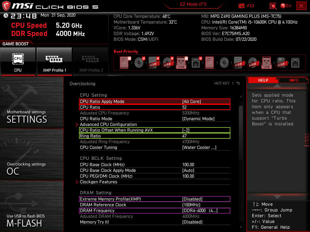
Starting with the CPU frequency marked in red in the image below make sure CPU Ratio Apply Mode is set to All Core and that the CPU ration is set to 49. Then Scroll down and select the CPU AVX offset to -1 or -2. Ring Ratio can be left on Auto and can be changed once the CPU overclock a 100% stable. Then marked in Purple is the DRAM settings unless you have a stable DDR4 overclock you want to turn XMP off and set the DRAM Frequency to the base speed of 2133 or 2400.
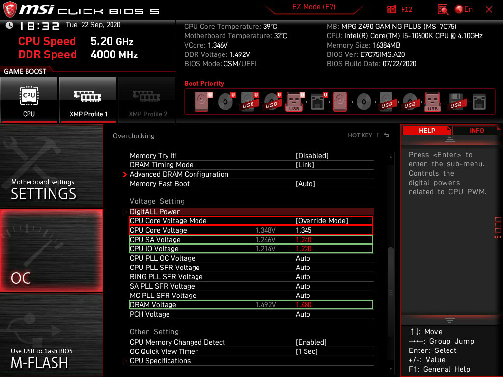
Scroll down, and now it is time to adjust the voltages. Since the 10600K is still on the 14nm node like the previous generation, the same voltage restrictions apply. Marked in red is the voltage settings for the CPU first unlock the voltage control but setting CPU Core Voltage Mode to Override Mode. This then allows the set that CPU Core Voltage. Take into account the table below as well as the binning information when setting your initial voltage. As an example below in red is the voltage for a golden chip reaching 5.2Ghz with 1.345Vcore. Marked in green are the voltages for DRAM overclocking you can leave these on Auto unless you have a 100% stable memory overclock.
Change the voltage to 1.25Vcore and daily in 49 in the CPU Core Ration marked in red in the above image. Press F10 to save and reboot the PC. Now you can run a quick CinebenchR20 to gauge if it stable at all if so follow up with five runs in Linpack Xtreme using 8GB of memory or more. If it crashes on either booting into windows or running a stress test, you will most likely end up in the 5.0Ghz to 5.1Ghz range. Important to note here that is also ties into the LLC level you selected for this overclock. Something you can also change and then try to run a short stress test.
When 1.25Vcore crashed at 4.9Ghz, then you can increase the voltage or lower the multiplier. The preference here is just increasing the voltage since you are far from the max allowed voltage for the 10600K. Enter a voltage of 1.275Vcore and reboot the PC and run a CinebenchR20 if that is stable run Linpack Xtreme stress test on 8GB of memory with five runs. To find the right multiplier with 1.275Vcore keep chancing the multiplier until it is stable. 1.275Vcore also does not generate a lot of heat, so should work with most CPU coolers and will provide you with a good indication of how high your 10600K can overclock.
The 10600K used for this guide ran 5.0Ghz on 1.245Vcore with a 46 multiplier on the Ringbus. Important to note here that when you change the Ringbus only do so after getting a stable overclock on the CPU. As well as this 10600K was unstable with a Ringbus multiplier of 47 but was stable with a Ringbus multiplier of 46. To illustrate how important it is to only change the Ringbus after your done overclocking the CPU. Validation with CPU-Z: CPU-Z 10600K @ 5.0Ghz and a CinebenchR20 score of 3861 so you have an idea how a stable 5.0Ghz overclock looks like.
To do an initial confirmation of a stable overclock run Linpack Xtreme with the same settings as before but this time around do it ten times and use HWiNFO64 to keep an eye on the temperatures and CVID(Vcore). Then you can go for a higher CPU overclock and try 5.0Ghz and 5.1Ghz but make sure to not thermal throttle the CPU, so you are limited by your cooling solution. As well as exceeding 1.4Vcore what would degrade your CPU and most of the time thermal throttle your CPU. Make sure you keep your AVX offset to -1 and -2 for chips that overclock really bad most of the times you won't need AVX instructions unless your rendering content for instance.
Some other tips are that IF you are not stable with 1.275Vcore and do not want to drop the CPU frequency you can increase the CPU voltage and reach a higher CPU overclock. The only limiting factors are your cooling capacity to prevent thermal throttling and staying below 1.40Vcore. Try 1.30Vcore for instance with your preferred frequency. To point out that 1.275Vcore is a starting point, not the end.
Once you have established the CPU overclock is stable, you can set a higher Ringbus. Most overclocks will end up with a Ringbus multiplier of 47 or 46. Ideally, you want the Ringbus to run 500mhz or less from the CPU Mhz. Taking this 10600K as an example, a Ringbus of 4700Mhz was stable with 5.1Ghz and 5.2Ghz but was unstable with 5.0Ghz. But you will have to stress test any changes in the Ringbus separately and including any CPU or RAM overclocks. Ringbus impact DRAM overclocking the most as well as reducing latency it can be left on Auto if neither is a concern.
To make sure your overclock is stable with acceptable thermals, you want to run a long stress test. As you want to test the AVX and none AVX stability of your CPU. Doing 20 runs of Linpack Xtreme and then a 1 hour run in Prime95 should be a confirmation your overclock is stable. Also, make sure the temperatures do not exceed 90C, aim for an 85C~90C thermals.
Prime95 you have two options simply run Small FFT's, but this will be a very heavy unrealistic load unless you render. You can also run Custom 8k FFTs so represent a more realistic gaming load. But make sure you do no exceed 90C in HWiNFO64.
Linpack Xtreme is excellent for really pushing your CPU and finding instabilities early on. Long Linpack Xtreme runs to confirm the overclock stable for long durations.
CinebenchR20, this is great to gauge your stability with a single click as well as using the scores to see if you get a better score. Scoring lower usually means that the overclock is or is becoming unstable.
For this particular i5 10600K, the max achievable overclock is 5.2Ghz with safe voltages and no thermal throttling. The Ringbus was set to 4700mhz with a 4000C15 memory overclock. Giving a CinebenchR20 score of 4015. The 5.1Ghz overlock is also linked with validation and has the same Ringbus and memory overclock. All overclocks included in this guide were extensively tested using Prime95, Linpack Xtreme, MemTest2, Aida64, MaxxMEM2 and CPU-Z.
Some quick stats for this overclocking guide for those just looking to get some of the numbers. These numbers are for this particular i5 10600K from Intel and mileage may vary based on your hardware and the silicone lottery.

- Paul "HisEvilness" Ripmeester.
This is a comprehensive and easy to use guide with illustrations to overclock the Ryzen 5 2600 CPU from AMD. This guide will cover the whole manual overclocking process and a quick guide for Precision Boost Overdrive 2.0 an auto overclock feature.
This will be the overclocking process for an AMD Ryzen 5 2600 on an ASUS X370 motherboard. This guide mainly covers the manual overclocking process as using AMD Precision Boost 2.0 yielded little results. AMD PBO 2.0 is covered in this guide for those unwilling to manually overclock their Ryzen 2600. When using a motherboard from a different manufacturer the voltages, core frequency and settings remain the same but might be found under a different naming convention. Depending on the quality of the board not all options might be present so mileage may vary in that regard.
Make sure you have the latest chipset drivers and other drivers for your current setup, Using outdated drivers may cause instabilities not related to your overclocking. Consider running a synthetic benchmark with stock settings to measure your gains. As well as if you intend to do any gaming have a baseline of FPS so you can see the increase.
You also want to download the following programs for stress testing your overclock. These are a vital tool for stress testing and monitoring if you already have tools you can use those but these programs I highly recommend and were used while writing this overclocking guide.

Zen + is a great improvement over the Zen 1 architecture so running DDR4 can be done with a QVL XMP profile. The ASUS ROG Strix X370-F Gaming is only validated for 3200 MHz but a good kit of 3466 MHz with Samsung B-die, Micron E-die or Hynix C-die(CJR) should be no problem. Important to note here that it is the Infinity Fabric that is unstable not the actual memory kit. However, higher speed kits might not run at the rated XMP speed it is therefore wise to test out any RAM kit first before applying any CPU overclock. If you can not run the rated speed, set a base speed of 2133 MHz. In the case of doubt stick to the QVL for your motherboard, a list of validated RAM kits can be found on the website for your motherboard vendor.

This is an AMD automatic overclocking feature while this did not return the results hoped for it was included in this guide to make it complete. For the best results ensure you have a 3rd party cooler and good case airflow.
There some settings in the BIOS that can be adjusted to use AMD's Precision Boost Overdrive 2.0 to gain the best results some tweaks are needed for a longer boost duration and overriding some limitation from within the BIOS.

These setting are important when preparing for overclocking your CPU and RAM. For this guide, only the CPU settings are important but there is a short run down for the SoC domain for memory overclocking. One important note here that Load Line Calibration(LLC) is set to level 4 with a max of level 5. This means there is a slight Vdroop under load with level 4, level 3 and lower will generate an even bigger Vdroop for this particular VRM.

There are 2 sections with some settings that will need to be turned off. These settings will hamper any manual overclock and may cause instabilities. Unless you want to use the AMD Precision Boost Overdrive feature as described in the above section.
Under AMD CBS turn off Core Performance Boost and Global C-State Control as shown in the image below.

Then go to Precision Boost Overdrive and turn that off as shown below in the image.

This is the overclocking part and the same voltage can be used to overclock both the 2600 and 2600X. Make sure you use save voltages for daily use in this case the consensus online is 1.38v for the CPU voltage. This used to be 1.40v however some Reddit users have commented on their CPU's degrading with voltages exceeding 1.38v. Higher voltages can be used for short term use with proper cooling for benchmarking and records.
There are 2 settings here that will be used the CPU Voltage(VDDCR CPU Voltage) and the CPU Core Ratio. For the core, voltage either use a Manual or Offset Mode voltage. Manual is easier to use and will be used for this guide. Offset Mode offers better granular control over voltage ensure however you keep withing save voltage limits.
SoC voltage does not apply with CPU overclocking it is used for FCLK(Infinity Fabric clock speed) and MCLK(Memory clock speed). If you experience instability from memory or infinity fabric tweaking this voltage can be helpful. A more in-depth guide for memory overclocking covering AMD and Intel systems link here: DDR RAM Overclocking Terminology FAQ & Overclocking Guide for DDR4 RAM. If you have QVL or none QVL memory and have instability issues with running the XMP profile reference this guide: How to stabilize DDR4 with Infinity Fabric
Since no PC build is the same start off with the highest recommend CPU voltage by AMD of 1.350v. This will also work for the AMD stock cooler but expect more fan noise then over more robust cooling like the Gelid Phantom Black used when writing this guide. Next is the CPU Core Ratio an easy overclock would be 4.0Ghz to achieve that fill in 40.00 in the CPU Core Ratio section. Save and exit and boot into Window. Now to confirm the overclock is stable either run Prime95 or Linpack Xtreme. For Prime95 use Small FFTs and have it run for at least 10 minutes. Linpack Xtreme you want to use the Stress test, use half the of the total capacity of your RAM using all cores and threads with at least 3 stress test runs. While doing so keep an eye on HWiNFO64 on core voltages and temperatures.

This should have passed either test you can now decide to keep the overclock at 4.0Ghz and tune the CPU voltage. The overclock of 4.0Ghz used in this guide used 1.269v with Load Line Calibration 4. If you want to go higher and go for 4.1Ghz then boot back into the BIOS and adjust the CPU Voltage to 1.38v with a CPU Core Ration of 41. This particular 2600 did not reach 4.1Ghz with a save voltage while it passed Prime95 it did not pass the Linpack Xtreme stress test so is not deemed 100% stable. In this case. the overclock was tuned the voltage for 4.05Ghz for daily use. And passed Prime95 and Linpack Xtreme stress testing.

Once you have set on a overclock for daily use and make sure it does not exceed 1.38v ~ 1.4v for daily use you want to do a final stability test. This is the final test to ensure you are 100% stable on the CPU overclock before moving on to for instance memory overclocking.
This is the voltage curve for this AMD Ryzen 2600 and it will be different per CPU. The main take away is that with the Ryzen 5 2600 the voltage wall is around 4.1 GHz. Important to note here again that more than 1.4 voltage is on the limit for Zen+ daily used and more then 1.38v is not advised.

- Paul "HisEvilness" Ripmeester
This is a short How-To fix AMD Ryzen with RAM issues on X370 that results in memory errors that will either prevent a PC from booting, the orange light blinking on the motherboard, the memory error Q-Codes. This works for Ryzen 1000 and 2000 series on X370 and B350 motherboards. Some QVL and none QVL RAM kits for a motherboard might have an issue with running the rated speed. This is the result of the Infinity Fabric not being stable, but the memory can run the rated speed. In the case of high-frequency kits over 3600 MHz running at a lower frequency with tighter timings is the only option but also improves performance over just running a higher frequency.
In short when looking to buy a RAM kit you want DDR4 memory kits that are 3200 MHz with C14, 3600 MHz with C15 or C16 and 4000 MHz with C17. In the case of buying a 4000 MHz kit for Ryzen, you only want to consider that if you intend to lower the frequency and tighten the timings. But this article is for those who already bought a memory kit but can not run it at the rated speed.
First, it is important to establish the quality of your RAM kit. Using Thaiphoon Burner to read on of your memory sticks. Important that QVL or none QVL is only important with Samsung B-die, Micron E-die and Hynix C-die. And then second the quality of those ICs this is translated into a low tCL speed in combination with higher frequency. First, start with reading one of the memory sticks with Thaiphoon burner.
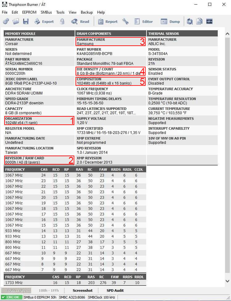
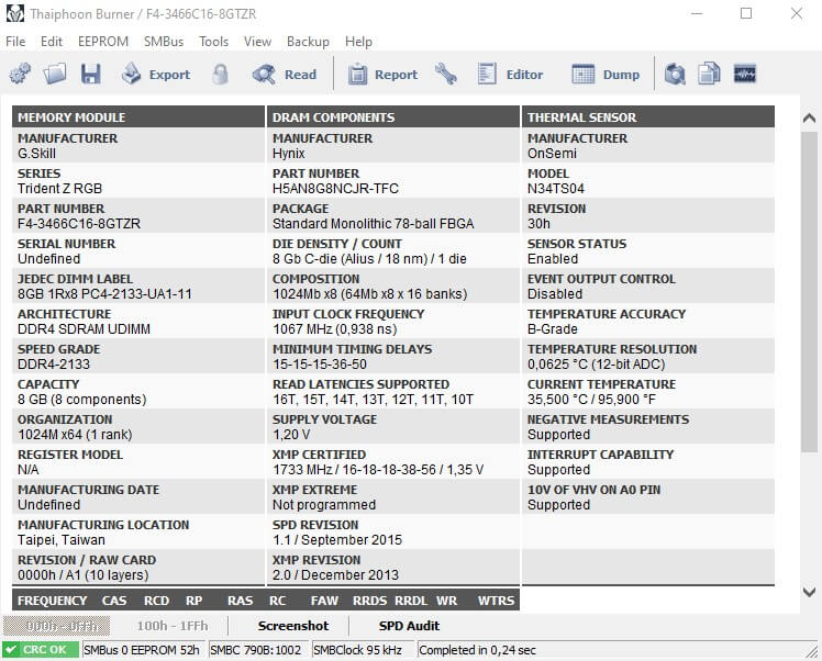
The information established here is when the RAM kit is not QVL you want to make sure under one is that you have one rank of modules, under two that the PCB quality is A0 or A1 with 8 or 10 layers on the PCB for signal integrity. That under 3 and 4 you have either have Samsung B-die, Micron E-die or Hynix C-die(CJR) and that under five it is confirmed single rank. This should make for a Ryzen friendly RAM kit even though it might not be on the QVL list of your motherboard. As an example below is a G.Skill RAM kit that is not on the QVL for my ASUS X370-F motherboard but with a bit of work it will run the rated 3466MHz speed with the XMP timings.
To have this kit run the rated speed and be stable by passing a Linpack Xtreme 10 run stress test involves four settings that have to be adjusted in the BIOS. The reason the PC is unstable is not so much the RAM kit is the Infinity Fabric that is unstable.
Starting with the important note that these settings are for XMP profiles if you want to overclock these settings will still apply; however, in different values.
Important to note that no RAM kit is the same so you will need to tinker with the ProcODT and CLDO VDDP Voltage. The above none QVL kit from G.Skill with Hynix C-die was stable with 1.1v SoC, 53.3 ohms ProcODT, 905mv CLDO VDDP voltage and Gear Down Mode enabled. No timings were changed nor was DRAM voltage increased this would leave room for overclocking the frequency or timings or even both. However, this would require more work and is not for everyone but is covered in separate articles linked at the top of this page.

And here is another none QVL kit this time from Corsair with Hynix A-die. To run the XMP profile stable 1.1v SOC, 53.3 ohms ProcODT, 920mv CLDO VDDP voltage and Gear Down Mode enabled. With this DDR4 kit, it is essential to illustrate that 5mv was the difference in being stable or unstable and how sensitive CLDO VDDP voltage is.

In some cases, random shutdowns might occur. This can be in combination with a CPU overclock. There are several issues related to unexpected shutdowns, PSU might be broken or of low quality, C-States of the CPU, ProcODT is too high or too low, and CLDO VDDP is too high to low. Take the following steps to troubleshoot.
It could be a combination of settings with my test rig it was a bad PSU that has less than 12 volts on the 12-volt rail for the CPU.
- Paul "HisEvilness" Ripmeester
This easy, comprehensive guide illustrated with images is for the overclocking DDR4 using several brands such as Corsair and G.Skill with different IC's as an example. This guide is to supplement existing DDR4 overclocking guides whose knowledge was combined with the experience of overclocking the various DDR4 kits listed below(more to come).
Listed below are the specs of the motherboards, DDR4 kits and CPUs.
HisEvilnes:
Nanogenesis:
There are several programs you need for stability testing, benchmarking, verification and a readout of your RAM IC's and PCB.
When purchasing a DDR4 RAM kit consider your capacity in GB as well as how many DIMMs it will populate. For overclocking a DDR4 kit of 2 is best however if you need more or just want more capacity with 32GB or more you can either end up with a 4 x 8GB kit or a 2 x 16GB kit. Most consumer CPU's will support dual rank like the Intel 9900k and the AMD 3600X. This means if you use more than 2 DDR4 sticks, you will share each channel. This will put more stress on the internal CPU IMC(Internal Memory Controller). Thus for extreme overclocking, Dual Rank DDR4 kits are better. When using Dual Rank kits, make sure you populate the 2nd and 4th DIMM slots or reference the motherboard manual.
Another consideration to make when using 4 DIMM slots on dual-channel motherboards is the topology of the motherboard traces. The traces leading to your DIMM slots can either be Daisy chained or use T-Topology. This is however not commonly advertised to guesstimate check the motherboard QVL. When the highest validation on the motherboard for RAM is with a kit of 4, then most likely that motherboard is using T-Topology. If the motherboard highest validation on the motherboard for RAM is with a kit of 2 sticks, then it is most likely Daisy chained. This is also a good indication of the motherboard quality. Even when using a RAM kit of 2 sticks, T-Topology is better for extreme overclocking(4000mhz or higher). But again for extreme overclocking it is always better to use two sticks of RAM on dual-channel for the best result.
This is the bread and butter of overclocking your RAM kit. The better your ICs and PCBs are, the better your overclocking potential will be. To verify what your PCB and IC's use Thaiphoon Burner and read one of your RAM sticks. Open Thaiphoon Burner and select Read then select any of the installed RAM sticks by selecting an SPD.

Now you will get a readout of your specific RAM stick, and this should be the same on all RAM sticks. To gauge the potential overclocking reference the example Thaiphoon Burner illustration.
So, in short, I have Samsung B-die in a single rank configuration of 1024 Mb IC's and an A0 PCB. With a total of 8GB per stick with four sticks, a total capacity of 32GB.
There are several PCBs for DDR4 some will be better for overclocking than others.
There is a wide variety of ICs by the three main manufacturers of IC's. Listed below are known ICs that are known to overclock. But some will do better than others. If your ICs are not listed below, they will most likely overclock poorly. Reference the linked DDR4 Overclocking Wiki for more specific details for specific IC's. Below is a list of ICs with a good overclocking potential mileage that may vary on the specific IC. For a more accurate list of DDR4 IC's please visit this Reddit article for a more in-depth picture of all available IC's: Reddit DDR4 IC listing.
| Expected Frequencies* | ICs | ||
| 4000 Mhz or higher | Samsung B-die | ||
| 4000 Mhz or higher | Micron E-die | ||
| Up to 4000 Mhz | Hynix C-die(CJR) | ||
| Up to 3600 Mhz | Hynix A-die(AFR) |
* Manufacturers do bin their ICs so adjust for expectations accordingly. A DRAM kit XMP rated for 3600 Mhz C18 will struggle to reach frequencies above 4000 Mhz unless you are really lucky. On the other hand, a DRAM kit XMP rated for 3600 Mhz C16 is of the finest binning and should only be limited by the maximum frequency your motherboard can handle.
For overclocking this will be vital as well as airflow to remove heat from the heat spreaders. RAM sticks without a heat spreader you will either have to install aftermarket heat spreaders or pass on overclocking. Having heat spreaders is also a good indication if they are meant for overclocking and the quality of the heat spreaders how well they will overclock. So expect to overclock results based on the quality of your RAM kit heat spreaders if your RAM kit comes with internal temperature probes you want to aim to keep them below 50c. ICs can take more heat, but some instability occurs after 50c that you will need to compensate for in more voltages or looser timings.
There are up to 3 voltages important for overclocking DDR4. For Intel System Agent, VCCIO and, DRAM voltages. And AMD SoC and DRAM voltages. These voltages help to stabilize the uncore domain of the CPU that ties into RAM as well as the RAM itself. The difference between Intel VCCIO and VCCSA and AMD SoC is that VCCIO requires an increase in voltage when increasing memory frequency in Mhz. And VCCSA requires a voltage increase when tightening timings.
| DRAM | - | Daily Driver | - | Extreme |
| Voltage | 1.20v ~ 1.45v | 1.45v ~ 1.60v |
Voltages exceeding 1.45v is only recommended for Samsung B-die for daily use up to 1.5v. To consider is that DDR4 kits with a rated 1.5v also have PCB's that can run that voltage as a daily driver. Extreme voltages for daily use is only wise if you can water cool your DDR4 kit.
| VCCSA | - | Daily Driver | - | Extreme |
| Voltage | 1.10v ~ 1.25v | 1.25v ~ 1.35v |
VCCSA also is known as System Agent voltage is for the IMC and PCIe domain. Going higher than 1.25v can damage the IMC and motherboard traces and is only recommended with high-end motherboards and short benchmarking and record attempts. System Agent voltages are commonly tied to tighter timings but lower speeds in Mhz. Using more System Agent voltage than needed for a overclock can cause instability.
| VCCIO | - | Daily Driver | - | Extreme |
| Voltage | 1.10v ~ 1.25v | 1.25v ~ 1.35v |
VCCIO is voltage for the IMC and using more than 1.25v VCCIO can damage your IMC and motherboard traces and is only recommended for high-end motherboards, and short benchmarking and record attempts. More VCCIO is needed for higher speeds in Mhz. Using more VCCIO than needed for a overclock can cause instability.
| SoC | - | Daily Driver | - | Extreme |
| Voltage | 1.00v ~ 1.20v | 1.20v ~ 1.25v |
SoC voltages help to reach higher FCLK(Infinity Fabric), MCLK(Memory Frequency) frequencies, and tighter timings. Extreme voltages are not recommended and are commonly used for HWbot extreme overclocking scores. And will require a beefy cooling solution if not exotic cooling.
To put these numbers into perspective here are some number from overclocking a range of DDR4 kits. Covering both AMD and Intel with their respective timings, frequency, voltages, and capacity.
| Frequency | - | Capacity | - | Timings | - | SA | - | IO | - | SOC | - | DRAM | - | Kit Number | - | CPU/Chipset |
| 4000 Mhz | 16 GB | 14-14-14-30 | 1.360v | 1.230v | ~ | 1.480v | F4-3600C15D-16GTZ | 10600K/Z490 | ||||||||
| 4000 Mhz | 32 GB | 17-17-17-34 | 1.216v | 1.216v | ~ | 1.450v | CMT32GX4MC3466C16 | 8086K/Z390 | ||||||||
| 3200 Mhz | 16GB | 12-12-12-28 | ~ | ~ | 1.231v | 1.500v | F4-3200C14D-16GTRS | 2600/X370 |
This guide will cover the main timings, and two secondary timings will get you little gains as well as you will either like working with 2nd, 3rd and 4th timings or you will hate it. For this guide, only primary timings and 2 of the secondary timings that will lower your Latency are covered. In due time this guide will be expanded to cover all timings.
All the primary Timings will allow for a performance gain in Read, Write and Copy speeds while tRFC and tREFI will lower the Latency of your memory kit. Read, Write and Copy represent raw performance in applications, thus more FPS or lower render times. While reduced Latency will make Windows more snappy as well as games being snappier, the is especially useful when gaming in a competitive sense.
The easy way is to save any overclock on other components like the CPU and GPU and then reset to default this will ensure that any instability while testing can only come from the RAM overclock. As RAM overclocking is time-consuming, it is wise to exclude any other factors of possible instability. Also, ensure that any overclock is saved in the BIOS to profile and well as any GPU to a profile. Also, make sure you have a baseline of the XMP profile from Aida64 or MaxxMEM2 with any CPU overclock applied since the memory OC will show a significant increase with or without a CPU overclock. And you also want a baseline to measure against when you revert all other overclocks. You can write down or save a screen capture of the Read, Write, Copy and Latency of the memory performance and use it as a reference when overclocking your memory. Reset the motherboard to default settings from within the BIOS before proceeding.

Runnings a 1:1 ratio with MCLK and FCLK is best for Ryzen. Only use higher RAM Mhz speeds when your infinity fabric can keep up. When maxing out the infinity fabric go for tighter timings as de-syncing will decrease performance.
Gear Down Mode is useful for reaching higher frequencies and can be seen as CR 1.5(T1.5/N1.5)but will lock out the option to select CR2. As well as forcing tCL to even numbers, for example, C15 is set to C16 with GDM.
CLDO_VDDG can in some cases help with stabilizing FCLK overclock on the Ryzen 3000 series. This only applies when manually adjusting both SoC and CLDO_VDDG voltages and should be done as a pair. With an SoC voltage of 1.10v, the CLDO_VDDG voltages will drop depending on the SoC LLC by roughly ~ 40mv to 1.01mv if left on Auto. So adjusting CLDO_VDDG manually you will have to ensure the SoC voltage drop under load is 40mv or less.
Increasing Ringbus clock speed will increase performance; however, make sure the CPU overclock is stable before overclocking the DRAM and after.
ASUS Maximus Tweaks will tighten RTLs and I-OLs values. Mode 1 works up to 4000Mhz and Mode 2 works above 4000mhz.
You are starting to overclock by simply booting into your BIOS and look for the DRAM, VCCIO, VCSSA and SoC(AMD) voltages. Make sure no XMP profile is selected and set the RAM profile manual. Also, check if MRC Fast Boot is turned off in the Timings section of your BIOS. Can be found in some high-end motherboard—Example BIOS from an ASUS Maximus Hero XI.

To start overclocking your DRAM you want to adjust your DRAM voltage to 1.45v for Samsung B-die and 1.40v for other dies like CJR, Intel VCCIO and VCCSA voltages to 1.15v or AMD SoC voltage to 1.10v. The following steps are in numerical order for overclocking gain.

Leaving all the timings to Auto you just want to increase the memory frequency with the voltages entered and see how fast your RAM kit can run. Depending on your XMP profile you want to start higher so with a 3200mhz XMP kit you want to start with 3600Mhz. If your RAM kit XMP profile is rated higher, you want to start 400Mhz higher than the base XMP profile. Make sure all the timings are set to Auto, which includes the Primary Timings, Secondary Timings etc. Just want to get the highest possible memory frequency and then work on the timings. With AMD Ryzen you want to set the FCLK half of your memory speed, so when using, for example, 3600mhz then set the FCLK to 1800mhz.

After selecting a frequency then save these settings in the BIOS and reboot. Your PC might reboot a couple of times adjusting the timings since you changed the frequency. If your RAM kit can run the speed, it will boot right into Windows. If it fails, it will show a failure to post a message. In the case of a failure, you can increase DRAM voltage for Samsung B-die to 1.50v and 1.45v for other dies. And adjust some of the settings listed below.

When it does boot into windows use Aida64 Cache & Memory Benchmark or MaxxMEM2 to gauge if your overclock is stable by checking the Read, Write, Copy and Latency. For Intel, you want a Latency between 55ns and 60ns without changing the timings and for AMD timings between 75ns to 80ns. And always an increase in Read/Write/Copy speeds. The first indication of instability is the memory having to correct for errors that will lower Read/Write/Copy speeds. You might also be able to boot into Windows, but when running a benchmark, your PC could shut down or BSOD which also is an unstable memory overclock. When using a Ryzen CPU, make sure you keep adjusting your FCLK to half the memory frequency. With booting or stability problems on Ryzen adjusting ProcODT and CLDO VDDP voltage will help stabilize memory overclocks. Important to note that CLDO VDDP is very sensitive, a 10mv range can be the difference between booting/unstable/stable.

Repeat this process to get the highest possible frequency on your RAM kit. Stop increasing the frequency as soon as it fails to boot into Windows or when you see a decrease in Read/Write/Copy speeds. Then you want to increase the DRAM voltage to 1.50v only for B-die or 1.45v for other dies if not already done so.
If you have not done so already. Also, something to look for the timings that are automatically set by your PC and make sure that those do not get overly loose. When you get a high frequency but your timings are so loose in the range of 25-25-25-50 or more you might want to consider running a lower frequency. With higher VCCIO, VCCSA or AMD SoC voltages you can try to keep the frequency that failed to post or did not return a better benchmark. But in general DRAM voltage gives a bigger boost and VCCIO, VCCSA and SoC help to stabilize overclocks that boot but won't pass a stress test. Below is a table of expected VCCIO and VCCSA voltages for AMD they are mainly tied to SoC voltage.
| Memory Frequency | - | VCCIO/VCCSA* |
| 3000 - 3466 Mhz | 1.10v - 1.15v | |
| 3466 - 3800 Mhz | 1.15 - 1.20v | |
| 3800 - 4200 Mhz | 1.20v - 1.25v | |
| 4200 Mhz and higher | 1.25v - 1.30v |
* Combining VCCIO and VCCSA works best for higher frequencies and their timings, for running 3200mhz with 14-14-14-32 as an example it is wise to drop VCCIO to 1.15v as it might introduce instability. For AMD SoC voltage a bit of similar advice when it comes to the Ryzen 3000 series. SoC voltage should not exceed 1.15v when only adjusting the frequency but can exceed 1.15v SoC to 1.20v ~ 1.25v SoC when tightening the timings of your DDR4 overclock.
| Memory Frequency | - | FCLK Frequency* | - | SoC Voltage |
| 3000 - 3200 Mhz | 1500 - 1600 Mhz | 1.10v - 1.15v | ||
| 3466 - 3800 Mhz | 1733 - 1900 Mhz | 1.15v - 1.20v | ||
| 3800 Mhz and higher | 1900 Mhz - and higher | 1.20v - 1.25v | ||
| Ryzen 3000 series | Any FCLK Mhz | 0.95v ~ 1.20v |
* FCLK should be synced with the memory frequency, and in all of the BIOS versions, I've seen this was done automatically. De-Syncing FCLK from MCLK could increase Latency and lower Read/Write/Copy speeds.
When you have established the highest possible memory frequency, it is time to tighten the timing. Here you start with the Primary Timings. To consider is that the best RAM kits run timings of 14-14-14-32 @ 3200mhz or 16-16-16-38 @ 3600mhz with 1.35v. This gives you a good indication of whatever max memory frequency you have for what memory timings you want to aim for and what is possible. Make sure the Command Rate is set to CR1/T1/N1 unless you are using a memory kit of 4 sticks then use CR2/T2/N2. If your timings on Auto went to CR2 regardless of the number of sticks keep these settings since using CR2 is slightly less demanding to overclock. You can consider using CR1/T1/N1 but expect less Mhz and loosen timings only really well-binned ICs do well on CR1.
For AMD Gear Down Mode can be enabled as well as adjusting ProcODT and CLDO VDDP voltage for AMD CPUs to help with stability, CLDO VDDG voltage can also be manually adjusted but make sure that SoC voltage is 40mv or more above CLDO VDDG voltage. As mentioned in the above paragraph regarding adjusting the frequency on the AMD 3000 series SoC should not exceed 1.15v when ONLY adjusting the frequency. However, when adjusting the timings tighter you can exceed the 1.15v for SoC as it will help stabilize your overclock in the 1.20v ~ 1.25v range for SoC this mostly applies to the AMD 3000 series. As SoC voltage has a wider impact on frequency and timings on the AMD 1000 and 2000 series as a whole. With the AMD 3000 series the impact has become far less but it could benefit from a slight boost in SoC voltage. As an example, an XMP kit of 3600C15 did run fine on 1.15v SoC using the XMP profile but when tightening the timings to 3466C14-14-14-28 SoC voltage had to be increased to 1.20v on the SoC or it would be unstable. With the AMD 5000 series, SoC has become very sensitive and changing it leads to instability very quickly. And with the 5000 series as an example with the 5800X, the SoC voltage is left on Auto and sits around 1.088 volts and changing the Switching Frequency and LLC in the VRM options yields great results for higher overlocks.
You can consider a wider range of overclocked profiles and pick your daily driver from there, but it will take considerable more time to test and stress testing each profile for 100% stability. And it must be said that stress testing is vital even if done for hours with Linpack, Prime95 at times you might find instabilities down the road, rare but it can still happen. In that case, some minor voltage tweaks could work but consider you might have to loosen or lower the frequency when it does happen.
Some important notes on adjusting the timings you want to make sure the 1st timing is only 1 or 2 steps away from the 2nd and 3rd timings. Only B-Die can run the same timings on the first three timings, for example, 16-16-16 for the first set. Other IC's you want to keep the first timings as low as possible but only loosen the 2nd and 3rd timing, as an example 16-18-18 for the first set. The 4th timing you want to double the 3rd timing and if needed to loosen + 4 steps ideally. Examples included in this guide are the most common used timings used for most IC's. It is, however, possible to run different sets like 14-15-14-31. However, this does not always work with a wide range of motherboards and DDR4 RAM kits. For this purpose, examples like 14-14-14-32, 19-19-19-38 and 17-19-19-38 are used since these always work on their respective DDR4 kits and all motherboards. Below are some more primary timings to consider as an example.
Example B-die Timings.
Example RAM Timings.

You want to keep making the timings tighter until the PC fails to boot or you start seeing a drop in Read/Write/Copy speeds in Aida64 or MaxxMen2. Adjusting Primary Timings will also lower the Latency, so there should also see a drop in Latency. The Latency of about 45ns is good, but you can get the Latency to drop below 40ns. In short, you want the Primary Timings as tight as you possibly can. If you want to make sure that these timings are stable you can run a demanding benchmark like Fire Strike Ultra in 3DMark. And do a 2 hours custom 512FFT to 4096FFT stress test before working on Secondary and Tertiary Timings.
The final timings you want to adjust are tREFI and tRFC these works best if adjust as a pair be can be done separately. The tRFC timing you want to lower as much as you can a tRFC of 300 or lower is very good, but this will also depend on the motherboard and RAM kit quality. Starting with a tRFC of 450 is a safe starting point and work the tRFC down as low as you can. tREFI is the opposite of all timings, and you want this value as high as you possibly can, some overclocks have a tREFI of 65000 or higher, but those are on the high-end motherboards like the Maximus Hero XI Extreme. And an easy tREFI to have stable is 25000. Adjusting tRFC and tREFI just like the Primary Timings by adjusting them until Windows fails to boot and/or the Aida64 or MaxxMem2 benchmarks show a drop in Latency but not an increase in Read/Write/Copy speeds.

Testing the stability of your memory is key, and this will be much harder than CPU and GPU overclocking as it is more time-consuming. This is different from your initial stability testing in the overclocking process and takes hours to complete.
Besides the synthetic testing, you want to run some demanding programs like games that make use of your RAM or applications such as video rendering if it is work-related. And look for stuttering in gaming, buffering speed while editing and rendering time. All in all, you want to see how your PC is doing after the overclock and that everything is fully stable.
When using Prime95, you want to run Custom Torture Test with large FFTs as shown below. 512 FFTs to 4096 FFTS and make sure you use at least 75% of your total memory capacity. So with a memory capacity of 16Gb, you want to at least run 14Gb or more. With a memory capacity, of 32Gb, you want to run at least 24Gb or more. Make sure that you leave some memory for Windows; Windows 10 needs at least 800Mb of memory. And you might want to consider running a hardware monitoring app like HWiNFO64 keeping an eye on voltages and temperatures. You want to complete at least 2 hours with no errors or longer stress test.
With overclocking any DDR4 kit comes trial and error this could present itself in BSOD, Watchdog and WHEA errors. To ensure your Windows stay healthy run CMD in Admin mode and running sfc /scannow to scan and fix corrupted files. This only takes a couple of minutes but it will ensure OS stability.

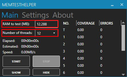
For the sake of certainty, a 2nd stress test was applied to the memory overclock using MemTest2 with MemTestHelper2 and is a highly recommend stress testing tool besides Prime95. The program MemTest2 is limited to only 2048MB per thread, and this is not the total capacity; it is the capacity used for each thread. When using an 8086k/8700k, you have six cores with 12 threads, and when using a 9900k, you have eight cores with 16 threads. So make sure you use all available threads. MemTestHelper should run at least a 350% coverage per instance, but more coverage in % per instance is better. When using MemTestHelper2, you can dial in the total capacity for RAM used for testing here you want to make sure you use 75% or more of your total capacity. Here you also want to make sure you run a hardware monitoring app like HWiNFO64 to keep an eye on voltages and temperatures.
On previous-generation CPU's from AMD on X370/B350 or X470/B360, some memory issues can occur when even running an XMP profile. You can find a separate article linked below that does not involve overclocking the RAM but adjust some minor settings to fix the problems that might occur with AMD Ryzen CPUs with QVL and none QVL DDR4 and can be found here: How to stabilize DDR4 with infinity fabric.
Listed here are some DDR4 RAM kit profiles with some of the timings. This is useful in case you have the same DDR4 kit while the silicone lottery still applies you can copy and paste some of the timings.
This kit from Corsair comes with a single-rank Samsung B-die and an A0 8 layer PCB and even comes with RGB. And two final stable overclock profiles were tested with a 3rd still in the works. The highest possible profile of 4266Mhz 17-19-19-38-CR2 with 400tRFC, 50000 tREFI with DRAM voltage of 1.465v, VCCIO and VCCSA voltages of 1.25v but failed the longer stress test of 2 hours and returned an error. Possible due to the fact B-die has instability issue's when reaching a temperature over 50c. In stress testing temperatures reached 58c on the inner 2 DIMMs.

The 2nd overclock profile was an attempt to get tight timings first and foremost and see what the highest possible frequency would be. This profile runs 3600Mhz 15-15-15-30-CR2 with tRFC 350, 50000 tREFI with a DRAM voltage of 1.45v and VCCIO and VCCSA voltages of 1.175v. This overclock profile passed the 2-hour Prime95 Custom FFTs test.

The 3rd profile is used as a daily driver and was the best possible trade-off in voltages, memory frequency and timings. This profile runs 4000Mhz 17-17-17-34-CR2 with tRFC 300, 60000 tREFI with a DRAM voltage of 1.45v and VCCIO and VCCSA voltages of 1.2v. This overclock passed a 2-hours Prime95 Custom FFTs and MemTestHelper2 350% coverage stress test.

The 4th profile is on an X570 ASUS Crosshair VIII Hero combined with a 5800X and runs a frequency of 3800Mhz with 16-16-16-32 timings, Command Rate 1 with a 1:1 Infinity Fabric of 1900Mhz with a DRAM voltage of 1.45.

This kit from G.Skill comes single rank Hynix C-die(CJR) and an A1 10 layer PCB with RGB. And has these stable overclock profiles tested. The highest possible frequency runs 3800Mhz 18-20-20-40-CR2 with tRFC 500, 50000 tREFI with a DRAM voltage of 1.45.

The 2nd overclock profile is an attempt to lower the timings to gain performance with memory frequency being secondary. This profile runs 3200Mhz 15-17-17-34-CR2 with tRFC 450 and 50000 tREFI with a DRAM voltage of 1.40v.

A G.Skill Royal kit that comes with single rank Samsung B-die on an A0 10 layer PCB with RGB. This kit has several stable overclock profiles tests. The 1st profile is on an X370 motherboard with a Ryzen 2600. Opting for real tight timings on the XMP frequency of 3200Mhz 12-12-12-28 CR1 with tRFC of 300 and a DRAM voltage of 1.5v.

The 2nd profile is Intel-based and centres around getting the highest possible frequency with the tightest timings. This profile runs 4000Mhz 16-16-16-34 with a 300 tRFC, 65535 tREFI with a DRAM voltage of 1.475v.

The go-to G.Skill kit when it comes to DDR4 overclocking with Samsung B-die has no RGB just a beefy heatsink. The highest possible profile and this was on a mid-range Z490 motherboard was 4200Mhz 15-15-15-30-CR2 with tRFC of 310, and 65000 tREFI with a DRAM voltage of 1.50v.

The 2nd profile was set to get very tight timings with the highest possible frequency. Even on a mid-range Z490, this is far easier and the overclock was locked in at 3800Mhz 13-13-13-28-CR2 with tRFC of 310, 65000tREFI and a DRAM voltage of 1.5v.

This kit comes with a dual-rank Micron E-die and a B1(Dual Rank IC PCB) PCB without RGB. And has two stable overclock profiles tested. The highest possible frequency profile runs in 3700Mhz 16-19-19-38-CR1 with tRFC 560, 28800 tREFI with a DRAM voltage of 1.45v.

The 2nd overclock profile is a to try to get the timings as tight as possible with memory frequency a secondary. This profile runs 3333Mhz 14-17-17-34-CR1 with tRFC 515, 11430 tREFI with a DRAM voltage of 1.45v.

- Good luck!
This Terminology FAQ covers overclocking for DDR RAM for both Intel and AMD platform and adds a reference material for various guides found on hisevilness.com. RAM overclocking can be time-consuming and involves a comprehensive set of knowledge with multiple settings mostly accessible through the motherboard BIOS. As well as some abbreviation you come across when reading up on DDR RAM overclocking.
DDR stands for Double Data Rate, and the number represents the version per JEDEC design. A RAM kit advertised speed is the speed in Mhz.
XMP profile is a unique profile that "overclocks" the RAM sticks above JEDEC spec(2133Mhz). This profile is always safe to use and is within the design spec of a specific DDR revision.
DIMM stands for Dual In-line Memory Module and represent the stick or sticks in a RAM kit. A DIMM slot is a socket that is DDR version-specific in pin layout on the motherboard.
A channel is a direct link from a DIMM slot to the CPU socket and therefor CPU itself. Also known as traces that represent the physical pathway in the motherboard. There are several Channel layouts, Dual-Channel where the CPU can fully utilize RAM sticks in Mhz slotted in at least 2 DIMM slots. Quad Channel usually found on HEDT can fully use minimal 4 RAM sticks in DIMM slots in Mhz. Channels can be shared, but this will sacrifice speed in Mhz and slightly increase latency.
An IC is the physical silicone on a PCB of the RAM stick that presents the capacity of a RAM stick. Multiple ICs make up the full capacity of the RAM stick and come in single rank(on one side of the PCB) or dual rank(on both sides of the PCB).
IMC stands for Internal Memory Controller and is located inside the CPU in the uncore/SoC domain. And handles communication with the motherboard chip, RAM, PCIe, IO etc.
NS stands for Nano Seconds and is the ability of a RAM kit to send and receive data in nanoseconds. Latency impacts the performance of read, write and copy speeds.
Is a motherboard trace layout that will allow for better 4 DIMM support on dual-channel CPU's. While still sharing one channel for 2 DIMM they are made in such a way that the signal is transmitted equally among both DIMMs.
Is a motherboard trace layout that allows dual-channel support CPUs to share each channel of a total of 4 DIMMs. This trace layout still favours the use of 2 DIMMs since the signal strength most commonly DIMM 2 and 4 is the best.
Voltages for DRAM according to JEDEC spec should be able to handle up to 1.5v, but this is not the case for specific ICs. While Samsung B-die can handle up to 1.5v the other Brand ICs such as Hynix or even Samsung E-die only can safely handle up to 1.45v. Higher voltages will require direct cooling such as water cooling with B-die over 1.5v and all the other revision of die over 1.45v.
| All IC's | B-die | |||
| DRAM Voltage | 1.20v ~ 1.45v | 1.45v ~ 1.5v |
DRAM VTT should not be mistaken for CPU VTT also known as VCCIO. DRAM VTT can help stabilize memory overclocks in combination with DRAM voltage. DRAM VTT should be half the DRAM voltage so as an example an XMP 1.35v DRAM voltage should be 0.675v DRAM VTT.
| Daily Drivers | Extreme | |||
| DRAM VTT Voltages | 1.1v ~ 1.25v | 1.25v ~ 1.4v |
procODT is found on AMD Ryzen CPUs. And dictates how a data signal is terminated after it is completed. You want a lower resistance(procODT) with lower memory frequencies and higher resistance(procODT) with higher frequencies. Changing procODT should be done one value higher or lower within the range of the table below.
| Memory Frequency | 3200 Mhz and Lower | 3200 Mhz - 3600 Mhz | 3600 Mhz - 3800Mhz |
| procODT | 40 ohm - 48 ohm | 48 ohm - 53 ohm | 53 ohm - 68 ohm |
CLDO_VPP is the voltage supply for the interface between the CPU IMC and the DRAM Modules. The DDR4 PHY as it is known is part of the SoC domain and translates signals from the IMC to the Memory sticks. The value for CLDO_VPP is in Mv and is limited to 1 volt. Changing this value helps to counter-memory holes and requires a cold reboot if adjusted. Lowering the CLDO_VPP is more common then increasing the CLDO_VPP. Changing this value should be done with care as it is very sensitive. So in short when a VLCO_VDDP value of 850 does not stabilize a memory OC the value should be raised initially by 15 ~ 20 mv to 865 ~ 870.
CLDO_VDDG is a new voltage introduced with the Ryzen 3000 series to help combined with CLDO_VDDP to help with the IMC. However, CLDO_VDDG is specifically for the Infinity Fabrics and is regulated from the SoC power rail. Since CLDO_VDDG is tied to the SoC voltage changing either of these voltages will change the other as they act as a pair. Thus when manually changing CLDO_VDDG and SoC voltages the CLDO_VDDG voltage has to be within ~40mv. Changing CLDO_VDDG does not always help but can help in some scenarios when overclocking the FCLK(Infinity Fabric).
SoC voltage is the same for all architectures with the Ryzen CPUs. And are used when overclocking the FCLK(Infinity Fabric) and MCLK(Memory Frequency). And in some cases can help to stabilize CPU overclocking.
| AMD | Community | |||
| Ryzen SoC | 1.000v ~ 1.150v | 1.150 ~ 1.250 |
Safe VCCIO and VCCSA voltages have been the same for about a decade and span several Intel nodes. Using extreme voltage could lead to damage of the IMC and motherboard traces.
| Daily Drivers | Extreme | |||
| VCCIO Voltage | 1.10v ~ 1.25v | 1.25v ~ 1.35v | ||
| VCCSA Voltage | 1.10v ~ 1.25v | 1.25v ~ 1.35v |
The primary timings of a RAM kit are always listed on the sales page and packaging. These numbers indicate the performance ability of a kit to transfer data, delay, pre-charge. The lower the number on the Primary Timings the faster your RAM kit can transfer data. Changing Primary Timings will impact latency and bandwidth. These are easily accessible in various tweaking software as well as in the motherboard BIOS.
Secondary timings are rarely found on marketing material. As with Primary Timings, they indicate the performance ability of the DDR kit to transfer data, delay, pre-charge. Lower Secondary Timings allow your RAM kit to transfer data faster. Changing Secondary Timings will impact latency and bandwidth. And they can be found in the BIOS of most motherboards.
Tertiary Timings are never found and are different per motherboard, CPU and RAM kit of the same manufacture and kit. They require special training from the motherboard, and this is the main reason your PC will reboot a couple of times when you install a new RAM kit. Lower Tertiary Timings impact bandwidth only and only high-end motherboards will allow you to change these timings.
Command Rate is not a timing but is listed in most marketing material and found under Primary Timings. It is accessible in most tweaking software and the BIOS with the Primary Timings. The number indicated the clock cycle needed to send and receive data from the CPU. CR is also known as T or N in the motherboard BIOS. And the number is clock cycle required to CR1 = 1 clock cycle. Changing CR impacts latency and CR1 is preferred over CR2. In contrast, CR1 is harder to overclock but has a 5% performance advantage over CR2. CR3 is commonly seen on HEDT with Quad-Channel.
These are latency settings and not timings and can be found under Tertiary Timings or a separate section in the BIOS of high-end motherboards. Adjusting RTL and IO-L should be done in sync. If not, it will increase latency and impede performance or even cause instability.
Is the voltage supply to your RAM, aka Memory sticks, increasing the DRAM voltage will allow your RAM to run at a higher frequency and tighter timings will increase heat output.
VCCIO voltage needs to be adjusted when increasing the Mhz of the RAM kit. Overshooting VCCIO can lead to instability; thus, it is wise to test the correct voltage since a overclock could be stable, but to high VCCIO voltage is making it unstable. A rule of thumb is that you will need 1.25v or more on overclock that exceed 4000mhz.
VCCSA voltage needs to be adjusted when using tighter timings at relative low memory frequency such as 14-14-14-32 @ 3200mhz. When using higher frequencies VCCSA needs to be modified when attempting to lower the timings, for instance, 17-17-17-34-C2 @ 4000mhz needs more VCCSA then 19-19-19-38-CR2 @ 4000Mhz.
SoC voltage needs to be adjusted with FCLK(Infinity Fabric),MCLK(RAM frequency), and RAM timings. So regardless of changing either of the settings mentioned above, SoC voltage will need to be adjusted.
Enables the memory to run half the average speed generated internally in MHz. Gear Down Mode can be seen as Command Rate 1.5. Enabling Gear Down Mode will prevent you from running Command Rated 2(T2/N2/CR2) and will only allow even tCL .
These common questions barely scratch the surface of DDR RAM overclocking but will help you get started in the future more information will be added, covering more in-depth topics.
- Enjoy overclocking, Paul "HisEvilness" Ripmeester

This is a guide to overclock the GeForce 1080ti from Nvidia. In this easy and comprehensive guide with pictures, the GPU clock speed, as well as GPU memory frequency, will be covered. As well as 2 methods for overclocking using direct clock speed and the clock curve methods will be shown. Furthermore, in this guide, 2 different GTX 1080ti's were used to gather data and reference material, the ASUS ROG GTX 1080ti Strix and MSI GTX 1080ti Gaming X.
You will need the following software installed:
This is the easiest method for overclocking your GTX 1080ti and depending on your software there some minute differences in dailing in settings. In this guide, 2 different utilities will be used as listed above. If you use a different utility your numbers and mileage might vary. All GTX 1080ti's are capable of reaching 2000mhz however depending on your variant triple fans vs dual fans, the fan curve might be different. The GTX 1080ti prefers to stay cool and beyond 40c you will lose voltage and clock frequency dictated by the GPU BIOS via the GPU Boost 3.0 mechanic that is hard locked into the GPU BIOS. Important to note that while you want to highest possible overclock, gaming next to a PC case that sounds like a lawnmower is far from ideal.
This section of the guide is for ASUS GTX 1080ti's using the ASUS GPU Tweak II utility. It is only recommended to use this for ASUS GPUs. Using the utility is straight forward and this guide will cover some of the default settings and overclock settings. You will need to start by going into Advanced Mode then selecting the Settings top right of the utility. Under the My Settings tick the box next to Overclocking range enhancements and click Apply to save the settings.

These settings are some of the default settings you will need to do some novice overclocking. You can also make a User Define fan curve to tune the noise level vs performance. It would be wise to save these settings so you can default back to them. Then you want to max out the following sliders.

This overclocking range should be well within the reach of most ASUS 1080ti's and is an easy stepping stone, you want to overclock the GPU first and confirm it is stable by using a benchmarking tool like Heaven. Add +95 on the GPU Boost Clock(Mhz) and click Apply. Now run Heaven benchmark but not in full screen so you can bring GPU Tweak II to the front. Let it run for a couple of minutes to level out the temperature and look for stuttering and artifacts.

Once you confirm it is stable you can try the following settings by increasing the GPU Boost Clock(Mhz) to +112 for an overlock of 2025mhz. Hit apply and run the Heaven benchmark. Let the temperature level out and again look for stuttering, artifacts.

The memory overclocking is simply done by moving the slider Memory Clock(Mhz) most GPU's will be able to roughly clock 6000mhz on the memory. But a good first step is to dial in +500 with the slider and run Heaven benchmark. To get to the 6000mhz memory frequency mark you can dial in +900 using the slider. And don't forget to apply any changes you make. Some 1080ti's can go as high as 7000mhz but this is extremely rare.
You can tweak the GPU even further but these are for the most part on a case by case basis. You want to increase +5 or +10 and run Heaven benchmark and look for artifacting or crashes to the desktop. As soon as you get any kind of instability you want to decrease the GPU clock speed -5 or -10 steps to previously used stable settings. Don't forget to run some game benchmarks that will give a good indication of how your 1080ti will do in-game. And also make sure you save some of your settings to profiles so you can keep using the overlocked settings.
This method works best if you are using MSI Afterburner since it gives better granular control over the curve. Using the curve method has more advantages over the sliders method since you will have a stable voltage, a higher frequency and slightly better temperatures since you will slightly under-volt. The GTX 1000 series has a default curve that has a base value of 40C. After the 40C threshold, you will lose voltage and 12.5mhz per 10C. In short, If you reach 2000mhz with a base temperature of 40C but the GPU heats up to 50C you will lose voltage and 12.5mhz. This will set your GPU clock speed to 1987mhz. The max voltage for all GTX 1080ti's set in the BIOS is 1.093v.
Before starting with this part of the guide make sure your GPU is below 40C this will set the GPU to the default voltage curve. This is very important or your overclocking results might suffer. Also, ensure your memory frequency is set to base value by simply resetting it. Below are 2 screenshots of the default voltage curve when the GTX 1080ti's are below 40c.


There are several settings you want to verify in MSI Afterburner with the following steps.
1.) Ensure Core Voltage slider is set to +100, this will ensure you won't lose voltage after 40C in your final overclock. Move the Power Limit slider to 120, this ensures max power draw per the voltage curve.

2.) In MSI Afterburner General settings make tick the Unlock voltage control & Unlock voltage monitoring and select third party table.

3.) Set an aggressive fan curve that will cool down your 1080ti between testing and ensures max realistic cooling under load. This differs per case, ambient noise, etc yours might differ. An even more aggressive fan curve could be used just for testing and benchmarking purposes.

For easier recovery save the default unedited settings with settings and fan curve applied to a profile in MSI afterburner.
Now open the curve editor by clicking CTRL+F and look for the 1050mv mark on the bottom and the 2000mhz mark on the side and drag the curve-point over the 1050mv line to the 2000mhz line. Don't worry about being exactly on the 2000mhz mark because as soon as you click apply in MSI it will default to the closest bin in this case 1999mhz/2000mhz. And exit the screen and click apply in MSI Afterburner.

The new voltage curve should now look something similar to the screenshot below. The curve should be a straight line to the right after 1050mv mark.

Now run Heaven benchmark and make sure that it is not full screen so you can bring MSI afterburner to the front. Check if the 1050mv and 1999mhz/2000mhz remain the same when the GPU is still below 50c. Let Heaven run for a couple of minutes until the temperature levels out.

Here you can see you lose 1 bin of 12.5mhz when the GPU heats up to 50c while retaining the voltage due to the curve method.

Now you open the curve editor again by hitting CTRL+F and drag the curve node to 2025mhz. Exit the curve editor and hit apply in MSI afterburner. Make sure the GPU is below 40c before starting the Heaven benchmark. Verify the 2025mhz and 1050mv numbers and let Heaven run for a couple of minutes again. You will lose 1 bin of 12,5mhz when the GPU reached 50C setting the clock speed to 2013mhz.

Open the curve editor again by hitting CTRL+F and drag the 1050mv node to 2050mhz. Exit the curve editor and hit apply in MSI Afterburner. Before starting Heaven benchmark make sure the GPU is below 40c. Here verify again the 2050mhz and 1050mv numbers. Let Heaven run for a couple of minutes so the temperature levels out. Here you will as well lose 1 bin of 12.5mhz when the GPU reaches 50c. For a clock speed of 2037mhz.

The ASUS ROG GTX 1080ti Strix used for the guide failed the 2050mhz/1050mv during more extensive stress tests while initially passing the Heaven benchmark. This would make it almost stable and would need adjustment to the curve to 1062mv. Reset MSI Afterburner and dial in the settings from the default curve as shown above. Make sure the GPU is below 40c so it will use the default curve. Open the curve editor by hitting CTRL+F and drag the 1062mv curve node to 2037mhz. Exit the curve editor and hit apply in MSI Afterburner. Run Heaven benchmark and ensure the 2037mhz and 1062mv numbers when the GPU is below 50c. When reaching 50c you will again lose 1 bin of 12.5mhz for a clock speed of 2025mhz.

This voltage curve is when you pass 2050mhz on 1050mv and the GPU remains stable during stress testing. This is the absolute limit and is only reserved for the top 5% GTX 1080ti's with triple fans or custom water cooling loops. Either reset MSI Afterburner and dial in the default curve settings as shown above. Or when using 2037mhz with 1062mv. Then proceed to drag the 1062mv node to 2062mhz. Then exit the curve editor again and hit apply in MSI Afterburner. Make sure the GPU is below 40C before starting the Heaven benchmark. Here you want to verify the 2062mhz and 1062mv numbers when the GPU is below 50c. Here as you will again lose 1 bin of 12.5mhz when the GPU heats up above 50c.

The 1031mv is best for dual fan GPU's that can not remain stable using the 1050mv curve. You want to get the default curve by resetting MSI afterburner and dial in the default curve settings shown above. And make sure to let the GPU cooldown below 40c for the default curve. Open the curve editor by hitting CTRL+F and drag the 1031mv node to 1987mhz. Exit the curve editor and hit apply in MSI Afterburner. Start the Heaven benchmark and verify the 1987mhz and 1031mv numbers. Let Heaven run for a couple of minutes until it levels out the temperature. You will here as well lose 1 bin of 12.5mhz when the GPU heats up above 50c with a clock speed of 1974mhz.

Tweaking the memory is the same as with the novice method. Simply use the slider to dial in +450 in MSI Afterburner and click apply. Use Heaven benchmark with your preferred voltage curve and let the benchmark run for a couple of minutes. Check for artifacts and stuttering. When the short test passes bump up the memory frequency +50 and run Heaven again, rinse and repeat until it fails. Most 1080ti's can reach a memory frequency of 6000mhz. But some GTX 1080ti's can go as high as 7000mhz on the memory frequency.
An important note regarding Heaven benchmark as you might have noticed that it will report a higher GPU clock speed then MSI Afterburner. This is due to the fact Heaven reports the maximum possible boost clock.
When you achieve your max possible curve now it is time to verify that is completely stable this will require a set of tests thus take some patience. First, you want to establish your maximum temperature by running a benchmark like 3d Mark FireStrike on a loop. Any game GPU heavy like Metro that has a benchmark will work as long as you strain the GPU. This will reflect an intense GPU gaming load, here it is important to remember that per 10c you will lose 1 bin of 12.5mhz. And most sustained loads will reach 70c on triple fan GPU's and 80c for dual fan GPU's. In short, when reaching a temperature of 70C or higher you will lose 3 x 12.5mhz bins. And when reaching a temperature of 80c or higher you will lose 4 x 12.5mhz bins. During the final stress tests the final fan curve that allows for the best cooling vs noise level. This will depend on the case, ambient noise, noise-absorbing padding if any and, GPU fan noise based on the type, size, number of fans and the type of ball bearings.
Important while doing your stress testing is looking for artifacting and stuttering or even crashing to desktop. If so drop 1 bin level on the preferred Mv curve. If that does not prevent any problems drop the memory frequency overclock by -100. If the memory overclock is stable see if you can go back up 1 bin on your Mv curve and test stability. This should lock in your best possible Mv curve and memory frequency overclock. Save this profile or make a note of the settings so you won't forget the settings.

- Paul "HisEvilness" Ripmeester & Nanogenesis
This FAQ will answer the most common questions when overclocking Intel CPUs. This will cover Intel-based CPU's over about a decade. For the most part, the same as with the AMD overclocking FAQ but naming convections might be different as well as a difference in the feature set you can find in the BIOS.
VRM stands for Voltage Regulator Module and is located close to the CPU socket to provide a reliable and clean power supply. The VRM regulates the power from the PSU. In overclocking you modify BIOS settings to instruct the VRM for increased performance at the expense of increased heat output. Motherboards for overclocking come with a high-quality VRM that uses better components. But a VRM always consists of MOSFET's, Chokes, Capacitors, and a PWM Controller. The IC(Integrated Circuit)is there to control and regulate those components.
These are Power settings that can be set through the BIOS and might different per motherboard vendor.
Power settings for the CPU with the standard set by Intel and depending on your motherboard quality may be adjusted to higher settings at the expense of increased power consumption and heat.
ASUS centric naming convention for a set of VRM controllers for overclocking PC components through software and BIOS.
The VRM controllers options found in the motherboards of MSI.
CPU LLC adds extra voltage to compensate for Vdroop when a CPU or GPU is put under heavy load. LLC gives overclocking stability by preventing low or high voltage fluctuations and tries to maintain a stable voltage supply to the CPU or GPU. Higher LLC tends to overshoot more in voltage supply and a lower LLC tends to undershoot in the voltage supply to the CPU. A general rule of thumb is when using LLC settings to select 1 level below the maximum allowed by your motherboard vendor.

It is a threshold for the VRM to shutdown and monitors the current supply to the CPU, setting Current Capability higher will allow for more current supply to the CPU but will increase heat output. This works best if you have an overclock that shuts down the motherboard/PC because the threshold is triggered.
Switching frequency is the transient response of your VRM MOSFETs settings this higher in Mhz will allow for a better transient response at the expense of increased heat output and using a lower setting in Mhz will lower the heat output but lower the transient response. Better transient response in overclocking translates into a more stable voltage supply from your PSU to the CPU.
This will allow for setting the current supply to the internal CPU voltage regulator at the expense of increased heat when set to extreme and lower heat when using optimized or standard. This will help with stability in overclocking and give the best result when using optimized or extreme.
This affects your VRM Power Phases to the CPU and will be depending on the setting, achieve greater stability in overclocking. Setting Power Phase Control to extreme keeps the number of active CPU power phases at the maximum. If you set Power Phase Control to optimized there will be a power-saving but less stability, phases to the CPU will power down.
This setting will impact the VRM based on temperatures and will throttle the CPU if the VRM gets too hot. To prevent throttling ensure you have airflow over the VRM heatsinks. Changing this setting to extreme allows for a greater thermal headroom when overlocking.
Ringbus or also referred to Ring Ratio is the internal CPU infrastructure that connects all the CPU cores, memory controller, system agent, IGPU, etc. Another naming convection is the uncore as in not the CPU core(s). Overclocking the Ringbus will result in a faster internal CPU data transfer but can lead to instability. An ideal Ringbus overclock is 1:1 with the CPU Core Ratio thus a 5.0Ghz(50.00 CPU Core Ratio). But in general, for stability, it is best to stay around 500Mhz of the Core Ratio. So a 5.0Ghz CPU overclock the Ringbus ideally should run at a Ringbus Ratio of 45(4.5Ghz). Ringbus OC is best served after overclocking your CPU and RAM for stability reasons. And the most gains will be in memory latency thus overclocking.

Sets the current limit for the CPU cores and Ringbus of an Intel CPU. This is to prevent throttling when overclocking thus only needs to be set when overclocking. Finding the maximum Current Limit simply enter 9999 and it will automatically set the max CPU Core/Cache Current Limit for you.
This value sets the time a CPU may run under load at the max possible boost frequency. When overclocking this value needs to be set at the highest possible value to maintain an overclock. This value is in watts and serves as a form of protection when overclocking. This value differs per CPU architecture and you can simply enter 9999 to automatically set the max Long Duration Package Power Limit.

This value is a time value in seconds that will impact how long a CPU can operate above TDP under load but below Long Duration Package Power Limit. Finding the maximum value simply enter 9999 and the highest possible value will be set automatically.
Sets a value in watts for the absolute highest power consumption for a short duration to compensate for Vdroop under extreme loads combined with LLC but is internal to the CPU whereas LLC is handled by the IC of the VRM. Settings this value to the maximum can easily be done by entering 9999 and it will automatically set the maximum value.
AVX is an instruction set used for certain workloads like video encoding. This instruction set is much more demanding and will in the case of overclocking generate more heat. To prevent instability or thermal throttling an AVX offset might be applied through the BIOS. Normal AVX offset is -1 or -2 so if a CPU is overclocked to 5.0Ghz but runs an AVX workload is will downclock the CPU to 4.8Ghz with an AVX offset of -2.
This allows the base frequency of 100 to be adjusted through the BIOS. Changing the BCLK frequency impacts all domains(core & uncore) of the CPU and rarely needs adjustments.
Cpu Core Ratio can on some motherboards be set per CPU core or synced on all CPU Cores. Sets the clock rate of your CPU by a factor of 10X. So a CPU Core Ratio of 50.00 will multiply the BCLK Frequency with a base value of 100 to 5,0Ghz.
Sets the voltage for your CPU and Ringbus on a 1:1 ratio, depending on your motherboard you can either enter a manual value of an offset value. So a manual value of 1.4000 will set the CPU voltage to 1.4 volts using the manual setting.
This voltage primarily is used when overclocking DRAM. And regulates the rail to the IO receivers in an Intel CPU. Adjusting this voltage may help with stability when overclocking your Ringbus and DRAM. In some cases such as the only CPU overclocking with the RAM XMP profile, a lower voltage might be applied to lower the overall heat output of a CPU.
This voltage is mainly used for DRAM overclocking and regulates the IO between CPU cores and the uncore. This voltage can be adjusted when the CPU has a weaker memory controller then normal and using a high-speed DRAM kit to gain stability.
PLL stands for Phase-Locked Loop and is the voltage control to the BCLK base clock, memory controller, bus clock and iGPU. These are different parts of the CPU and have their own frequencies. CPU PLLs voltage only needs to be changed is you change the BCLK clock speed or are using exotic cooling and running into the infamous Cold Bug.
Is the voltage supply to your RAM aka Memory sticks, increasing the DRAM voltage will allow your RAM to run at a higher frequency at times without changing the DRAM Timings but will increase heat output.
This sets the idle states of a CPU when it is not executing commands there a various C-States and serve as a power-saving function. For overclocking this should be turned off since you want maximum performance at the expense of increased power consumption and helps with keeping a stable overclock.
These are the most common questions and settings when overclocking an Intel-based system and served a supplement for current and upcoming overclocking guides for Intel-based systems. This FAQ is to supplement those guides and serve as a reference to more technical clarifications.
- Paul "HisEvilness" Ripmeester

This is a short article with great FREE SEO tools for 2020. With the recent Google updates such as BERT some great new additions to the 2019 list of tools. To sound in 2020 and some SEO optimization for your CMS or custom coded website. All tools listed are Free or have a Free option that could be converted into a paid option with more features. This 2020 article is a follow up from my 2019 SEO tools with some new tools as well as some tools that remain vital for 2020 in terms of SEO. The big chance for 2020 is the more prevalent use of rich snippets by Google as well as other search engines and their BERT update that will allow Google to better answer user search queries. But many other tools remain included in this list for all your SEO needs.
These tools are the same for 2020 as with 2019 but will offer more features with rich snippets being widely used by Google and being implemented with Bing, Yahoo, and Yandex. 3 search engines allow you to submit sitemaps and analyze your site performance based on their ruleset. These are powerful SEO tools in itself because the data comes straight from the source. Important to note here that with Bing that they provide the data for Yahoo as well. Data mine search results that apply to your website and the number of clicks you get from search results. As well as showing the number of pages from your website that have been indexed or ignored or have errors. And do not forget to submit your site map so the crawl bots will visit your site sooner than later.
These tools are specific to Google as they involve the schema.org and AMP. While other search engines make use of these features and any mobile device can make use of AMP. These tools are to test and verify your structured data as well as AMP conical pages. This is very important as errors may result in delisting from search results ensure if you use structured data that you maintain the outlying rules set by Google as you may be penalized if caught.
Several websites offer several services and result to analyze the various aspects of your websites such as loading time, minifying various coding aspect such as .css and .html as well as the number of requests. An important ranking factor in SEO is the loading speed and content optimization. As well as some aspect to indicate the end-user experience something that has become a more important ranking factor over time, this includes meta and title description and the structure of your website. The most important ranking factor to consider is that for Google since that yields the most traffic for your website but it is wise not to neglect the other search engines and consider them.
Everything for backlinks and SEO related data linked to links, the amount of external and internal links, new links and lost links with that sprinkled in some content analysis with your links. Important to know who links to your website and if they do link to what page. Collecting links is vital for your growth as well as being a ranking factor in SEO. Here are some great free tools that allow you to give a better break down of links to your website and links within your website.
See how your content stacks up in the world and see what the trends are. Very important for SEO even more so if you want to take a deeper dive into SEO. These are the tools to find the trends related to the content of your website and search queries from users.
Images make up the larger portion of your website site there for it will impact your SEO score if you do not optimize them. These tools will ensure you will keep your quality images but reduce their size so your website will load faster. What is also important is a favicon for your website in various sizes and a search engine to see who is using your images on the web. Great free tools to help you optimize your end-user experience.
Some other tools that I consider to be vital for use in SEO they fill in a niche you won't find on any other the other categories. Ranging from Content Delivery network to a sitemap XML generator and a little tool that pings various crawl bots that you have updated your website content all in all these tools should give you an extra edge when it comes to SEO.
These handy tools will allow you to collect user data such as e-mail addresses and enable push notifications. This outreach then can be used to convert traffic to sales or returning traffic by allowing you to notify subscribed users of updates, new content and new products.
So here you have it a comprehensive list of SEO tools for 2020. The updated list for 2020 includes many tools you need with Google updates. Many of these tools will only need to use once or twice when initially writing your content such as the structured data test. Other tools like optimization are an ongoing effort and it is wise to check at least once a month on your search performance. Another important tool for optimization is the analyzers for backlinks and keywords for improving current and upcoming content for your site. In any case, I hope this article is helpful to you.
- Paul "HisEvilness" Ripmeester

A FAQ for reference when working with Samsung Galaxy devices and, how to gain root access and flashing Custom or stock ROMs. A short-list of common questions for people who are new to working with TWRP, Odin and, Magisk.
This FAQ is writing concerning the following articles found on my website.
Samsung Galaxy J6(2018) guide to Root and Custom ROM
Samsung A3/A5/A7 2017 Root & Android Oreo 8.0 OS upgrade Tutorial
Guide to custom recovery and root on the Samsung Galaxy series.
TWRP is an open-source project custom recovery utility that allows end-users to install a custom OS or software on their phones and, also provide recovery options and, allows users to enable of root on a phone. This is for all Google android based devices including phones and tablets.

Odin is a ROM flashing utility for all Samsung android based devices. This, in short, allows you to upload custom software to your Samsung Android-based devices via your PC or Laptop.

Magisk is an open-source utility to gain root access to your phone without tripping the security that is needed to run apps like banking software.
ROM stands for Read-Only Memory and is the portion of your devices where your Android OS is located you can change a stock ROM to a custom ROM changing the operating system.
Rooting is gaining administrator priveledges on your Android-based device to modify code. A manufacturer does not allow it by default since it may damage your device if done irresponsibly.
Depending on your device either hold Volume Down + Power button + Home button or when there is no Home button hold Volume Down + Power button or, Volume Up + Volume Down + Insert USB.
Depending on your device either hold Volume Up + Power button + Home button or, Volume Up + Power button.
If bricking occurs soft brick is the most common kind of bricking. This happens when there your phone keeps boot looping so it powers up and, then at some point switches off and powers up etc and, keeps doing that in a loop as well as crashing on boot giving errors etc.
Hard bricking is rare but it means your device won't even boot and, keeps flashing the Samsung logo and, won't power down, or won't show more than a black/grey or a battery screen when connecting a USB cable. Recovery from this is harder and your only chance of recovery is slim since it can also mean there might be hardware damage however hardware damage is extremely rare.
- Paul "HisEviless" Ripmeester


